-
-
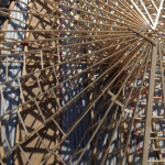
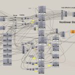
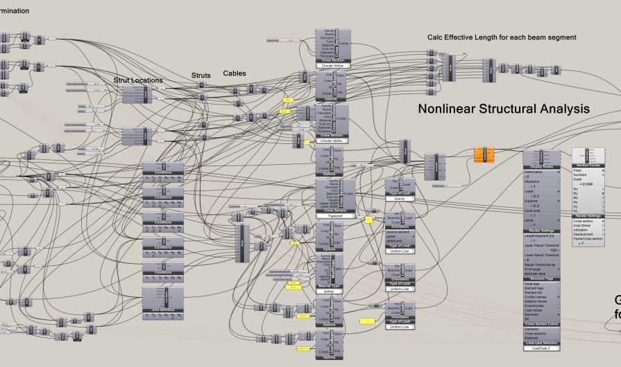 Grasshopper Script which performs cost and structural optimization of a hybrid glulam and steel kingpost truss. The script defines parameters which can be changed such as truss depth, and then uses an Evolutionary Algorithm to search the parameter space and determine the lowest cost structure.
 -
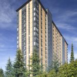
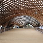
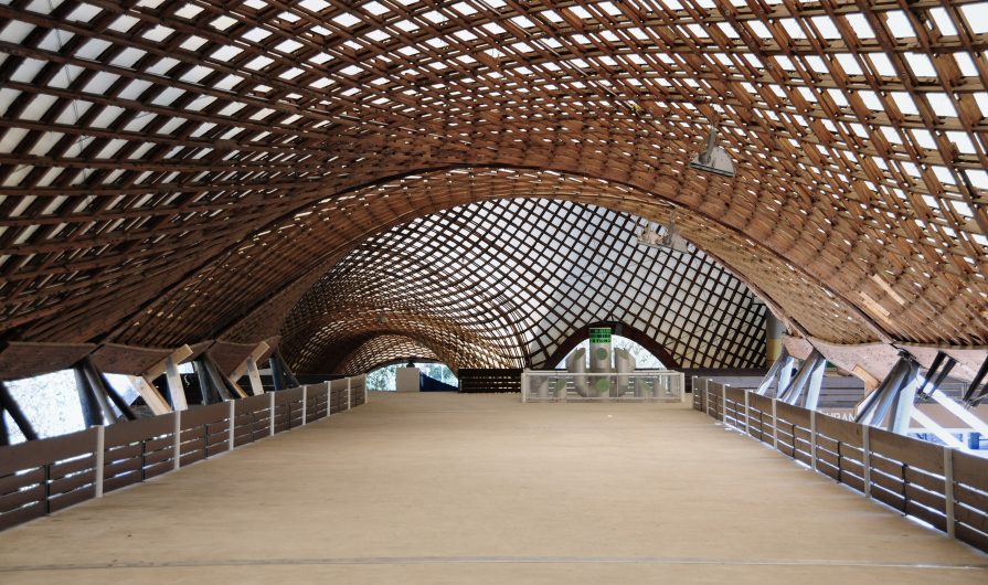 Mannheim Gridshell, Germany
 -
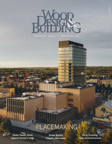
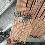
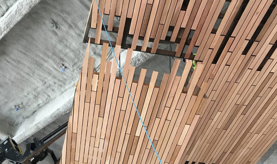 Installation of pre-fabricated panels.
 -
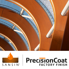
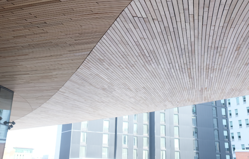
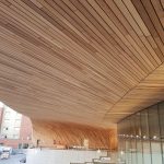
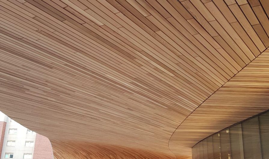 Doubly curved soffit at the New Calgary Library created using a geodesic batten pattern.
By Lucas Epp
Over the last 10 years, the field of computational design has taken the building industry by storm. The meteoric rise of this new paradigm amongst designers can largely be attributed to the emergence of new user-friendly software tools. These tools enable the creation of parametric scripts by designers, without requiring computer programming skills. Use of computational design has now become de rigueur in leading architectural and engineering practices worldwide, particularly in geometrically complex or freeform structures.
These software tools encourage a design approach which defines the geometry of structures parametrically – the guiding geometrical principles of a design are exposed as parameters which can be changed at any point during the design. This enables rapid exploration of variations on a certain design or geometry.
Significant advances in software design over the last 10 years now allow real-time analysis to be performed as the geometric parameters are changed. As an example, this means that a designer, while changing the depth of the kingpost truss to the right, can watch in real-time as the structural forces change. This is a step change from traditional analysis methods which involve transferring geometry to a separate analysis software, and then running analyses often taking minutes or hours.
The design-performance feedback loop has thus been reduced from hours to seconds.
RECENT COMPUTATIONAL DESIGN
Depending on one’s definition of computational design, it arguably started even before the first CAD software – Alan Sutherland’s SKETCHPAD (1963). However in the architecture, engineering and construction (AEC) industry today, the term typically implies using computing to influence or enable the exploration of design space.
The possible applications of computational design are almost limitless; it is not limited to parametric geometrical investigation, and can be used for true generative design, where a computational algorithm generates the forms by following a set of rules.
However, computational design in architecture and engineering has been primarily focused on the parametric definition of geometrical form, and the performance evaluation of such forms. The ability to quickly assess the performance characteristics of designs while varying design parameters can greatly aid design selection.
Early parametric CAD tools like Bentley’s GenerativeComponents first started gaining popularity in 2005, particularly in London’s architectural community. With the release of Grasshopper (a plug-in to Rhinoceros modelling software) in 2007, it quickly became the norm for parametric modelling and computational design in the AEC world. Other software tools like Autodesk’s Dynamo have built on the success of Grasshopper.
These tools use a simple node-based interface, called visual programming – each node on the canvas shown above performs an operation, taking inputs on the left and giving outputs on the right. For example, a Line node would take as input 2 points, or a Structural Beam node would take as inputs a collection of Lines, a Cross Section, and a Material. The topology of the wires connecting the various nodes defines the algorithm logic, thus creating a script.
Inside computational software tools such as Grasshopper, robust user communities have contributed custom plug-ins enabling diverse types of computation and analyses, ranging from geometrical to mathematical to machine learning.
The performance characteristics of buildings which can be evaluated are extensive, including daylighting and building energy simulation, people movement, structural finite element analysis, CNC robotic simulation and toolpath generation, geometric analysis and optimization (e.g. for freeform facade panel planarity), form-finding (e.g. hanging chains a la Gaudi), and physics simulation including Computational Fluid Dynamics.
In the field of structural engineering, computational design is often used for optimizing the geometry or topology of a structure to achieve the most structurally efficient or lowest cost structure.
FREEFORM TIMBER
With timber as a natural material, there is a long history of designing and building complex or free-form shapes and structures of varying sizes. The flexibility and workability of the material makes it ideal for shaping and milling, but its natural defects and variability also present challenges in predictability.
Perhaps some of the earliest structures built using wood curved into shape are the indigenous dwellings constructed with bamboo, reed, and hardwoods in places like southern Iraq (Mudhif houses), Ethiopia (Dorze tribe houses), and Brazil (Oca houses).
In the 1960s, Frei Otto pioneered the use of timber for freeform gridshell structures, using the so-called bending active technique: a lattice of initially straight timber lathes is laid flat on the ground and then curved up into place on-site. After success with smaller structures at Expo’ 67 Montreal, his crowning achievement was the Mannheim Multihalle (1975), an interconnected series of spaces created by a bidirectional double layer grid of 2″ x 2″ timber lathes, with clear spans up to 200 ft – a span-to-depth ratio thinner than that of an eggshell.
In the 1990s, Julius Natterer explored timber gridshells using elements which were initially curved in one direction and then allowed to torque about their long axis during installation, creating structures with larger structural depths and spans, culminating in the Expodach Hannover in 2000.
Both of these approaches, however, limit the geometrical form of the roof because the amount of curve or twist that can be placed in an initially straight timber element is limited. Another approach to creating truly freeform roof structures was explored with the Pompidou Metz (Shigeru Ban, 2010). Instead of using initially straight small cross-section lathes, much larger straight elements were used, with each piece three-dimensionally CNC-milled into the required twisted, curved shape to suit the geometry of the roof. Since this project, further advances in glue lamination have enabled the automated production of initially doubly curved Glulam elements, removing much of the wasted material created by CNC-milling an initially straight element. Several timber gridshells have been built worldwide using a similar strategy.
Apart from gridshells, continuous freeform cladding surfaces are increasingly interesting to contemporary architects. Much has been done with materials like glass reinforced concrete (GRC) and metal panels. More recently, timber as a material for large-scale freeform cladding has gained significant attention.
STRUCTURE
Inside Grasshopper, structural analysis of a structure with 20,000 elements can be calculated in <0.5 sec – effectively real-time. This allows for rapid exploration of different structural configurations. Using the example of the hybrid kingpost truss, over 100 analysis runs per second of this simple structure are possible using the script shown, allowing thousands of different configurations to be explored in a matter of minutes.
Model-based or metaheuristic optimization techniques such as evolutionary algorithms can then be used to iterate the selection of design parameters toward a structurally optimal solution.
After the structural analysis has been run, the resulting structural forces can be used downstream to automatically size the elements and calculate material usage or cost. This gives the designer immediate feedback on important attributes of the structural configuration.
COMPLEX
One useful aspect of computational design with timber is enabling structural analysis and automatic generation of fabrication information for geometrically complex projects.
The freeform soffit for Calgary’s new public library forms a doubly curved underbelly and entrance to the building. The surface is created with Western red cedar battens; the battens are initially straight, and are bent and twisted as they are applied onto panels, following minimum energy curves known as geodesics across the surface. To apply these battens in place would have been impossible both from a labor and an accuracy standpoint. Prefabrication was a must.
To create the complex geometry, the soffit is built with prefabricated panels, with the battens attached to a ribbed structure of CNC’d backing elements. Over 20,000 unique pieces of CNC-profiled wood form the 300 panels in this structure. Each panel spans up to 25 feet, connecting to each other and curving down toward the ground, creating an entrance intended to attract the public into the building.
Computational design was critical in enabling the 3D geometry creation, structural analysis, CNC milling data, and fabrication drawings for this project. Custom algorithms were written to randomize the position of batten joints across the soffit, while respecting fabrication constraints such as the maximum overlap between panels. A parametric 3D modelling approach allowed rule sets for the prefabricated panels and battens to be established and then automatically produce 3D models and fabrication information for each of the 170 panels.
Computational design on this project enabled a vertically integrated approach, linking design, engineering, and fabrication information. As the overall geometry of the surface changed throughout the design, both structural analysis and generation of fabrication information was automatically updated.
SIMPLE
Naturally, computational design has found earliest adoption in complex projects. However, the principles of computation are not limited in scope to the complex.
For simpler structures such as mass timber, parametric design and analysis can be used for anything from helping determine optimal column grids or structural configurations to automating the creation of 4D models (construction of a structure through time), simulating CNC machine toolpaths, or to simply parsing and displaying data about the geometry or structure of a building in a graphic and interactive manner.
CONCLUSION
Use of software tools often associated with computational design enables projects with significant complexity, but is not limited to these. Using node-based visual programming, computational design approaches can be applied simply to many different problems.
Interest in using timber for structures both complex and simple is increasing. A focus on off-site and modular techniques in timber construction makes computational design well-suited to this field, and its use will continue to grow significantly in North America and abroad.
Lucas Epp, P.Eng., leads the Engineering department at StructureCraft Builders Inc. He can be reached at lepp@structurecraft.com or (604) 313-2526.