-
 Wellington Secondary School. Photo Credit: Artez Photo.com
Jim Taggart
To understand the principles of seismic design, one must first understand the nature of seismic forces. Initiated by the movement of the Earth’s tectonic plates, they take the form of waves that travel either in the body of the planet or at its surface. Body waves are further subdivided into primary (P) waves – behaving like the repeated compression and release of a spring – shaking a building in the horizontal plane, and secondary (S) waves – transverse in nature – shaking a building in the vertical plane.
As knowledge of earthquake behavior has evolved, more sophisticated approaches to the seismic design of buildings have been developed. An important consideration is that of ductility. In the case of major earthquake events, the energy-dissipative components are designed to perform ‘plastically’ – absorbing energy through deformation and permitting a certain level of damage to the structure, but preventing the catastrophic collapse of the building. In typical wood buildings, the main source of ductility are the connections. (Even after moderate earthquakes, it is prudent practice for building owners to have an inspection carried out by a qualified structural engineer to ensure that the integrity of the structure has not been compromised).
Although seismic events occur all over the world, the areas most susceptible to large earthquakes lie along the boundaries of tectonic plates, including those on the so-called ‘Ring of Fire’ encircling the Pacific Ocean and passing through British Columbia.
British Columbia’s seismic upgrade program
With several major earthquakes having struck other countries on the Ring of Fire in the past two decades, there is a heightened awareness of the risk faced in British Columbia. A survey commissioned by the provincial government and conducted by the Association of Professional Engineers and Geoscientists of British Columbia (APEGBC) in 2004 determined a significant number of older BC schools did not meet the then-current safety requirements in terms of seismic design.

The “Ring of Fire” encircling the Pacific Ocean
Of these, 339 were found to include structures in the highest risk category (known as H1) – those most likely to experience widespread and irreparable damage or structural failure in a seismic event. In response to these findings, the province initiated a seismic upgrade program, which has retrofitted or replaced 224 of the highest risk schools in 37 districts to date. A number of these projects used wood as the primary structural material. (The seismic mitigation program and the associated risk categories are described on the province of British Columbia website. It is important to note classifications are applied not to schools as a whole, but to ‘blocks’ within the building. Blocks represent areas within a school that are of different construction types and have different structural characteristics. For example, gymnasiums will typically have a different structural system than classroom or administration blocks, and as a result may have a different risk rating).
Seismic upgrading of
Wellington Secondary School
Located in Nanaimo on Vancouver Island, Wellington Secondary School is a two-story, 115,712-sq.ft. structure with a capacity of 900 students. It was built in several phases from 1969 to 2000, on a radial plan with a circular central block – known as Block F – surrounded by five other blocks (Blocks A, B, C, D, and E).
Seismic assessment
and design approach
In 2012, structural engineers from Nanaimo-based Herold Engineering prepared a Seismic Project Investigation Report identifying four of the blocks (all except C and D) as risk category H1. Two seismic mitigation options were considered: comprehensive upgrades to bring all the structures up to current code standard; or a partial upgrade, together with the demolition and replacement of the highest risk portions of the building (Blocks A and F).
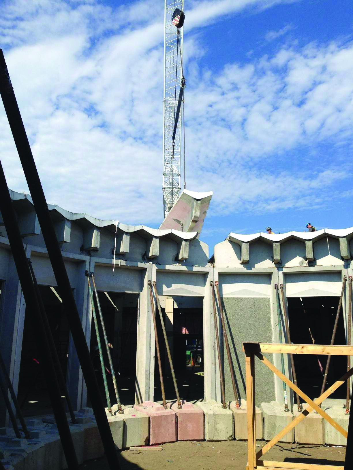
Wellington Secondary: dismantling of Block F. Photo Credit: Herold Engineering Ltd.
More detailed consideration of site constraints, the provision of temporary classroom accommodation, parking, site access, and staging confirmed demolition and rebuild was the more economical option.
This option included the seismic upgrades of Blocks B, D, and E, the demolition and rebuilding of Block F, and the demolition and replacement of Block A with a new classroom block (in another location referred to as Block G).
The upgrading of Blocks B and E were carried out at the beginning of the renovation. Both had been constructed in 1987 with a combination of precast concrete panels, unreinforced (or partially reinforced) concrete masonry unit (CMU) walls, and heavy timber roofs with glued-laminated (glulam) beams, tongue-and-groove decking, and plywood sheathing. The seismic upgrade included additional reinforcement of the masonry walls, higher ductility connections between the walls and roof, and the strengthening of the roof diaphragm with an additional layer of plywood. (Cross-laminated wood products, such as plywood and CLT, are particularly well-suited to use as diaphragms as they resist racking when subjected to lateral forces).
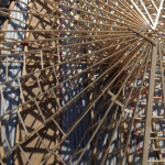
Seismic analysis of Block F
The original 1969 library structure (Block F) presented a considerable challenge to upgrade, and the analysis merited a more detailed discussion. The roof structure consisted of radially arranged concrete T-beams, resting on inner and outer concrete ring beams supported on concrete columns. In turn, these columns were supported on concrete walls at the basement level. The entire structure was heavy and, having been designed to a much less demanding seismic standard, had neither the required ductile connections between the elements nor the adequate lateral restraint in the radial direction.
Generally, when comparing two buildings of equal height, in the same geographic location, and with the same soil conditions, a heavier building will attract larger seismic forces than a lighter building. The heavy weight of the Block F structure would have required a large number of custom steel brackets, substantial cross-bracing, and enlarged foundations to transfer the required loads to the ground. The more desirable, and cost-neutral, alternative was to dismantle the existing structure and replace it with a new lightweight building.
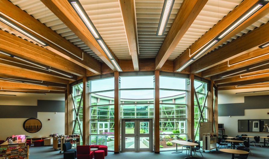
Wood was chosen for this replacement structure due to its economy, speed of construction, and esthetics. The wood solution met the constraints of a fast-track schedule and a tight budget, while introducing a warm look to the core of the school. Demolition of Block A opened up an area adjacent to this core that is now a new glazed entrance.
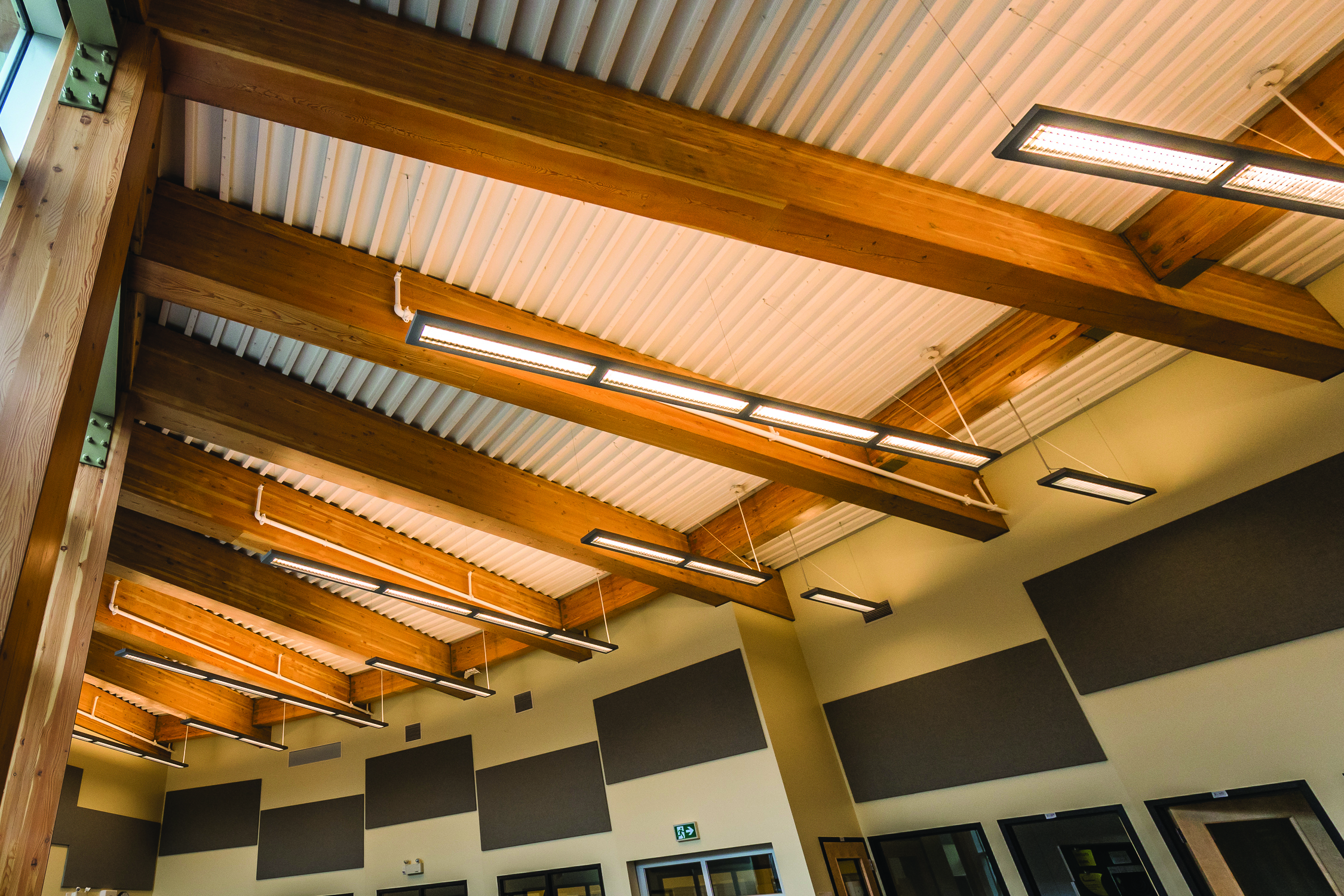
Wellington Secondary: New structural members in Block F. Photo Credit: Artez Photo.com
Detailed design
The structural engineers developed a retrofit system for Block F that used the existing foundations and replicated the geometry of the original structure. Block F is divided into two distinct but connected components. The ‘main street’ surrounding the central courtyard forms a circle with an inner and outer ring of columns connected by beams that support a sloping roof. The inner ring of columns delineates the exterior glazed wall that encircles the courtyard, while the outer ring forms a colonnade separating the main street from the rest of the school.
The main street is circular in plan, and the surrounding school is in the form of a pentagon, leaving an irregularly shaped zone between them. This zone was covered by an existing flat roof originally framed with solid timbers. The longest of these members were reinforced with laminated veneer lumber (LVL) beams, so the roof could perform as an effective diaphragm between Block F and the surrounding blocks. The engineers also added a second layer of plywood sheathing to meet load transfer and drift requirements.
This upgraded roof connects to the outer ring of posts below the eave line of the central sloping roof. This results in a discontinuous section where the roof diaphragms are not in the same plane, requiring lateral loads be transferred into the vertical structure by a pair of drag rings consisting of continuous steel cross-bracing.
In the vertical plane, lateral resistance is provided by a series of 16 steel cross-braced frames that tie into adjacent pairs of glulam columns in the outer ring. Full-height cross-bracing is also used between pairs of columns in the inner ring. Throughout the timber structure of Block F, connections are designed to be relatively simple and economical – the majority being exposed steel plates and brackets.
The light weight, versatility, and economy of wood have combined to bring this project to a successful resolution, on time and on budget. Wood has also contributed additional value, creating a warm and welcoming atmosphere, one that has transformed the identity of this aging school.
Other applications
of wood in seismic design
Two other recently completed BC school projects illustrate alternative approaches to seismic design using wood. Cordova Bay Elementary in Victoria employs a combination of cross-laminated timber (CLT) and nail-laminated timber (NLT) panels, while Surrey Christian School combines a glulam post-and-beam system and light-wood frame shear walls with NLT roof panels.
CLT and NLT panel solutions
Cordova Bay Elementary dates from 1945, and like Wellington Secondary, has undergone multiple renovations and expansions since. Of these, the 1965 addition, constructed with unreinforced concrete masonry exterior walls and a glulam and heavy timber roof, was designated as risk category H1.
As with Wellington, a detailed assessment of site logistics temporary accommodation resulted in the decision to replace the existing structure. It was proposed the new classroom block be built with CLT walls and roof panels, and light-wood frame construction for interior non-loadbearing partitions.
Despite the replacement option having been chosen for its low cost, the project came in a little over budget. The low bidder for the supply and installation of the CLT components, offered a savings to change the roof panels to NLT. The final result is all the loadbearing and shear walls are constructed from five-ply CLT, and the roof is NLT panels made from 2 x 8-in. material nailed together face to face, creating a solid deck.
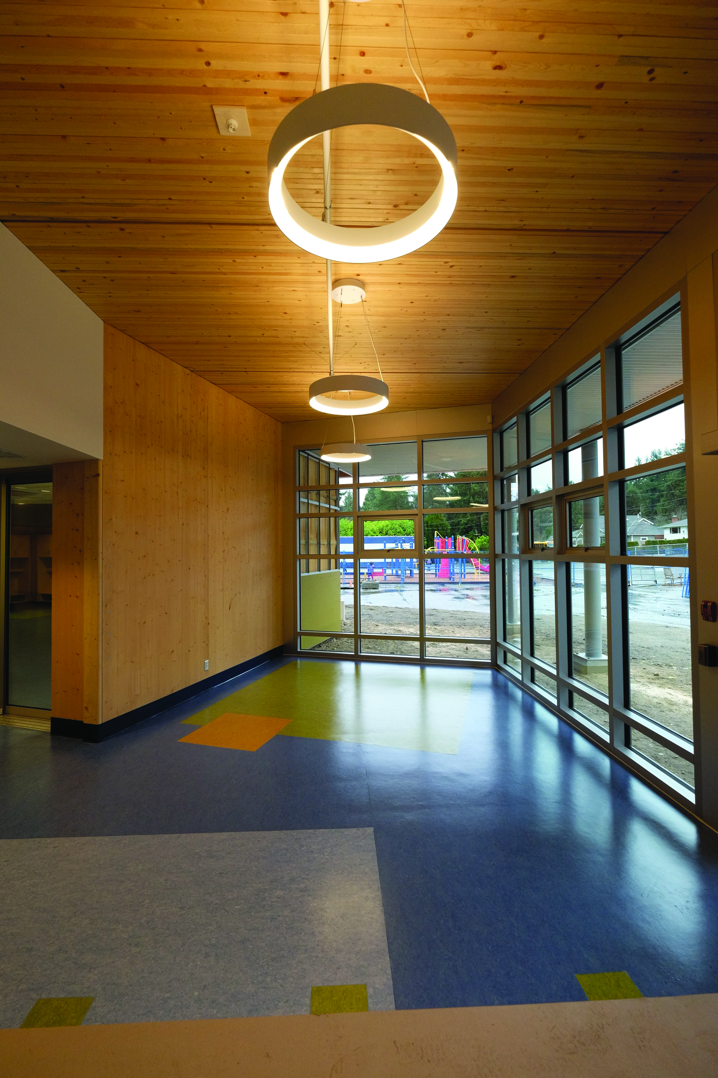
Cordova Bay Elementary School: Interior of lobby showing exposed CLT and NLT panels. Photo Credit: StructureCraft Builders Inc.
The CLT panels are set vertically, extending from the ground floor slab to the underside of the roof. Base connections are steel plates set into the concrete and recessed into rebbates factory-milled into the panels. The plates are secured using long, high-strength, self-tapping screws, then covered with a wood plug so the connections are hidden and the CLT can be left exposed.
The vertical edges of the panels are milled with a profile so they form a lap joint when brought together. This joint is then stitched together using pairs of similar self-tapping screws set at opposing angles. Where an internal wall meets an external wall, the butt joint is secured in the same manner. The use of a large number of small connections (rather than a smaller number of large connections) is the most efficient way to dissipate seismic forces. This is because it spreads the load more evenly through the structural section.
The NLT panels bear directly on the CLT walls and are connected to them in a similar way. They arrive onsite with a plywood diaphragm factory installed over most of the panel, but held back from the edges. The panels are lifted into place by a crane, and the diaphragm is completed by installing a final row of plywood sheets that cover the joint between panels. This approach results in a continuous diaphragm across the entire roof, requiring only a single layer of plywood.
This project demonstrates that factory-produced CLT and NLT panels can be successfully combined to create economical and esthetically pleasing buildings. It also confirms simply detailed CLT panel systems can provide a cost-competitive, code-compliant solution for lateral design in high seismic zones.
Glulam post-and-beam and
light-wood frame shear walls
Located in the Lower Mainland, the new two-story Surrey Christian School building includes a total of 15 daycare, kindergarten, and primary classrooms, along with their support spaces. The classrooms are organized along a linear two-story atrium extending the full length of the building.
The need to connect at main floor level to the adjacent middle school meant the new building, which is on a sloping site, was constructed atop a new single-level parking garage that is partially tucked into the hillside.
To address the client’s concerns for economy and speed, and deliver an attractive, high-quality building simultaneously, the design team proposed a simple engineered wood post-beam-panel structure that could be prefabricated.
The vertical structure consists of glulam posts at 8.8-ft. centers along the length of the building. Each bay consists of four posts – two at the exterior walls and two at the atrium walls. The glulam posts were factory-fitted with custom steel base plates that were attached using long, high-strength, self-tapping screws installed at opposing angles.
The posts on the main floor were bolted to the concrete slab of the parking structure, and braced longitudinally using light-wood frame infill panels. There are no longitudinal beams in the building. The posts were then ready to receive prefabricated floor and roof panels, 8.8 ft. in width and spanning the full 27.8-ft. depth of the classrooms. Each panel has two glulam edge beams, connected with light-wood frame header panels at both ends and bridged by a deck made up of nail-laminated 2 x 4-in. material.
These panels were installed in alternate bays along the length of the building, leaving the spaces between them to be filled with a second panel type that consisted only of 2 x 4 nail-laminated timbers. The edge beams of the main panels rest directly on top of the posts, and are connected to them with a similar detail to that used at the base.
Once all the main floor panels were installed, plywood sheathing was laid by the general contractor in order to create a horizontal diaphragm. (Carpenters used plywood reclaimed from the formwork for the concrete parking garage. It was field-installed one sheet at a time). For the vertical plane, lateral stability is achieved by plywood-sheathed light-wood frame walls running north-south at either end of the building, and east-west along the length of the corridor between door openings. These shear walls were also prefabricated. The lateral system was designed to resist all the required seismic loads, enabling the exterior walls of the classrooms to be fully glazed.
For this project, the use of factory prefabrication compensated in part for the additional time required to construct the parking garage. It was possible for the wood components to be prefabricated at the same time as the concrete was being poured. Installation of all the prefabricated wood components took approximately one week. Prefabrication in wood was also compatible with the use of site-built light-wood frame construction for the interior partitions. The result is a building with a warm and welcoming atmosphere that greatly exceeded the client’s expectations.
A final note
The projects described in this article were all designed to meet the requirements of the 2012 edition of the British Columbia Building Code (BCBC), which was based on the 2010 edition of the National Building Code of Canada (NBC). It is worth noting the seismic design values used in the new 2015 edition of the NBC (upon which subsequent editions of the BCBC will be based) are significantly higher than those in the 2010 edition of the code. Therefore, the solutions described here may not comply with those more stringent requirements – although new solutions using the same basic principles will of course be developed. (Of course, designing structural wood buildings goes far beyond solely seismic requirements. For more information, see this author’s previous Construction Canada case studies and articles, including “Mid-rise Makeovers,” by visiting www.constructioncanada.net. Other features of interest would include “Specifying Combustible Construction in Canada” by Jack Keays, MSc., P.Eng., and “Specifying Modern Timber Connections” by Maik Gehloff, Dipl.-Ing. (FH), M.A.Sc. For further reading, also visit www.constructionspecifier.com for the article, “Solid Timber, Solid Construction Performance,” by Ryan E. Smith).
This article originally appeared in the May 2016
issue of Construction Canada (vol. 58, no. 3),
the official publication of Construction
Specifications Canada (CSC). For more information, visit www.constructioncanada.net.
Jim Taggart, FRAIC, teaches architecture at the British Columbia Institute of Technology (BCIT) in Vancouver. He is also the editor of Sustainable Architecture and Building Magazine (SABMag) and the author or editor of more than a dozen books, including the award-winning Toward a Culture of Wood Architecture (2011). Taggart has also lectured extensively on this subject throughout North America, Scandinavia, and Australasia. He is a Fellow of the Royal Architectural Institute of Canada (RAIC) and the recipient of the 2012 Premier of British Columbia’s Wood Champion Award. He can be reached at architext@telus.net.